 Updating a telescope
 Updating a telescope
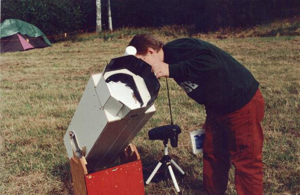
by Nils Olof Carlin (member of SAAF). Click for larger images! The one above shows solar viewing at the Mariestad star party, sept 2nd, 2000)
The telescope in question is one that I built for my brother 5 years ago - in one weekend! The optics, a 10.1" Coulter mirror with secondary, were bought second-hand. The tube is made of 1/8" plywood, of the cheap kind used to cover walls, with a printed paper finish. This makes for a light tube - the total weight, including finder but not rockerbox, is 23 lbs (10.5 kg). There is an internal "diagonal cage", that holds the focuser, spider, finder etc. The spider is my "hacksaw" design described elsewhere, with vanes of 2 mm aluminium (perhaps overkill, but spikes are no big problem).
After these years (I have spent a couple of them with the ATM list), it was obvious to us that a few things could be improved:
I wouldn't cram this update into one weekend, but on the other hand I like to keep things simple. If there is an inexpensive way that works OK, I prefer it. So here are some of the old and new features - simple and inexpensive to make, and useful, I hope.
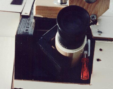 The focuser: We wanted easy access to the
eyepiece, at any altitude, sitting comfortably. To me,
this means a focuser mounted at 45 deg to the altitude
axis, at the left side as I like to have the telescope to
the right of me. I had to cut off a corner of the
internal diagonal tube to make room for its base. I have
tried before -with no success then- to make a
Crayford-like focuser with Teflon bearings, but having
seen one made by the Uppsala people, I tried again. The
focuser board is detachable, and held by 3 screws.
Standing on it is a 50 mm (2") high "V" of
12 mm (1/2") plywood, with inner surfaces of
laminate (the same as used on the trunnions)for the
drawtube to slide against. The focuser drawtube is a
piece of 40 mm PVC drain tube, about 70 mm long, with a
1.25" i.d. insert for the eyepiece. A 4mm screw in a
threaded hole holds the eyepiece. Below the insert, the
inside of the tube is covered with black self-adhesive
flock plastic. I have taped a piece of Teflon sheet (the
kind that has recently been popular for altitude
bearings) around the tube, to make it slide smoothly. The
focuser axis in this image is a cheap screwdriver with
about 3 mm dia. shaft, cut to size.
The focuser: We wanted easy access to the
eyepiece, at any altitude, sitting comfortably. To me,
this means a focuser mounted at 45 deg to the altitude
axis, at the left side as I like to have the telescope to
the right of me. I had to cut off a corner of the
internal diagonal tube to make room for its base. I have
tried before -with no success then- to make a
Crayford-like focuser with Teflon bearings, but having
seen one made by the Uppsala people, I tried again. The
focuser board is detachable, and held by 3 screws.
Standing on it is a 50 mm (2") high "V" of
12 mm (1/2") plywood, with inner surfaces of
laminate (the same as used on the trunnions)for the
drawtube to slide against. The focuser drawtube is a
piece of 40 mm PVC drain tube, about 70 mm long, with a
1.25" i.d. insert for the eyepiece. A 4mm screw in a
threaded hole holds the eyepiece. Below the insert, the
inside of the tube is covered with black self-adhesive
flock plastic. I have taped a piece of Teflon sheet (the
kind that has recently been popular for altitude
bearings) around the tube, to make it slide smoothly. The
focuser axis in this image is a cheap screwdriver with
about 3 mm dia. shaft, cut to size.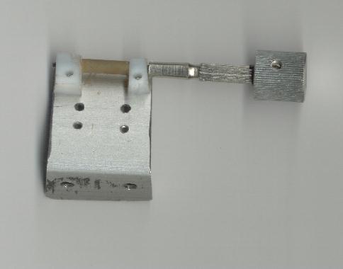
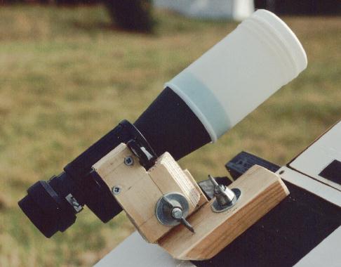 The finder: It is made from 12 mm plywood and
wood, joined together by 8 mm bolts and wing nuts to each
other and to a plywood base, part of the internal
diagonal cage. Spring washers (not shown) makes it easy
to adjust, and the wing nuts are tightened to lock. This
image shows the first version as it is a bit simpler, but
if you look at the tube extension image, you see a
version where the finder is rotated 90 deg to make the
eyepiece better accessible while seated for observing.
That way, I can go from the eyepiece to the finder by
leaning a little back, without having to leave my seat.
The holes from the hinge are useful for coarse aiming,
but later, a red-point 1x finder will be added. I have
fastened the flat side of the prism housing using two
self-tapping screws - I made sure they did not hit the
prisms! The dewcap is a plastic medicine bottle, with the
protective lid on during solar observing.
The finder: It is made from 12 mm plywood and
wood, joined together by 8 mm bolts and wing nuts to each
other and to a plywood base, part of the internal
diagonal cage. Spring washers (not shown) makes it easy
to adjust, and the wing nuts are tightened to lock. This
image shows the first version as it is a bit simpler, but
if you look at the tube extension image, you see a
version where the finder is rotated 90 deg to make the
eyepiece better accessible while seated for observing.
That way, I can go from the eyepiece to the finder by
leaning a little back, without having to leave my seat.
The holes from the hinge are useful for coarse aiming,
but later, a red-point 1x finder will be added. I have
fastened the flat side of the prism housing using two
self-tapping screws - I made sure they did not hit the
prisms! The dewcap is a plastic medicine bottle, with the
protective lid on during solar observing. 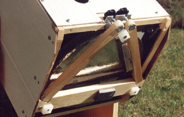 The
mirror cell: I would not consider a mirror cell
that I can't collimate while looking into the Cheshire or
eyepiece. The original one had a 9 point cell, with a
closed back that took a bit too long to cool. Thanks to
PLOP, the program by David Lewis, we know that that 6
points is even better than the traditional 9. It is certainly much
simpler mechanically, the way I did it now. The optimum
radius for a 6 point cell is about 0.6 of the mirror
radius, but I used 0.7 for a mechanically simpler design,
the performance is still more than adequate according to
PLOP. The square wooden frame is screwed to the tube
sides. The 3 "see-saws", carrying two cork pads
each, are made from 20x20 mm aluminium "T"
profile, and fastened with wood screws acting as hinges
(only one is visible here).
I haven't (out of laziness, perhaps) jumped on the RTV
bandwaggon, so I use a sling arrangement - not the usual
one, but instead two slings between opposite corners,
each making a 90 degree turn:
The
mirror cell: I would not consider a mirror cell
that I can't collimate while looking into the Cheshire or
eyepiece. The original one had a 9 point cell, with a
closed back that took a bit too long to cool. Thanks to
PLOP, the program by David Lewis, we know that that 6
points is even better than the traditional 9. It is certainly much
simpler mechanically, the way I did it now. The optimum
radius for a 6 point cell is about 0.6 of the mirror
radius, but I used 0.7 for a mechanically simpler design,
the performance is still more than adequate according to
PLOP. The square wooden frame is screwed to the tube
sides. The 3 "see-saws", carrying two cork pads
each, are made from 20x20 mm aluminium "T"
profile, and fastened with wood screws acting as hinges
(only one is visible here).
I haven't (out of laziness, perhaps) jumped on the RTV
bandwaggon, so I use a sling arrangement - not the usual
one, but instead two slings between opposite corners,
each making a 90 degree turn:
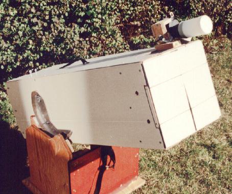 The tube extension: This feature is left from
the original model. 4 flaps cover the tube opening in two
complete layers. Each flap is divided into 3 parts joined
by fabric "hinges" (thick fabric and strong
glue), and the middle part is hinged to the tube (or
rather to the diagonal cage). I have used fabric here,
too, but metal hinges will probably be more durable (they
could be epoxied to the thin flaps). In use, the side
flaps are held together by Velcro pieces, forming an
octagonal tube whose length is half the tube width, in
this case 6", 152 mm, making the tube 6"
shorter for transporting (it is 41", 1030 mm now).
This image shows it closed, you can see it open on other
images.
The tube extension: This feature is left from
the original model. 4 flaps cover the tube opening in two
complete layers. Each flap is divided into 3 parts joined
by fabric "hinges" (thick fabric and strong
glue), and the middle part is hinged to the tube (or
rather to the diagonal cage). I have used fabric here,
too, but metal hinges will probably be more durable (they
could be epoxied to the thin flaps). In use, the side
flaps are held together by Velcro pieces, forming an
octagonal tube whose length is half the tube width, in
this case 6", 152 mm, making the tube 6"
shorter for transporting (it is 41", 1030 mm now).
This image shows it closed, you can see it open on other
images.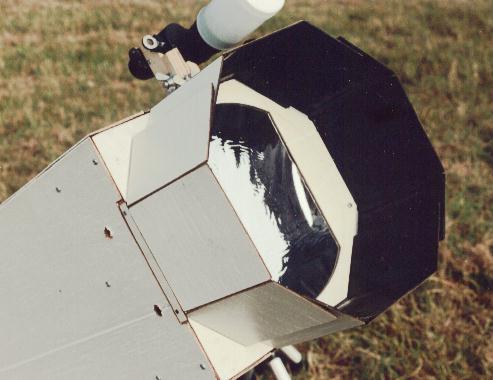 The solar
filter: It is made from Baader AstroSolar film,
fastened to a plywood frame with a thin string of glue
(contact cement). It is secured in place with 2 screws
(it must be removed before the tube extension flaps can
be closed). As you see, the filter is not quite wide
enough to cover the full aperture, but this is no
problem.
The solar
filter: It is made from Baader AstroSolar film,
fastened to a plywood frame with a thin string of glue
(contact cement). It is secured in place with 2 screws
(it must be removed before the tube extension flaps can
be closed). As you see, the filter is not quite wide
enough to cover the full aperture, but this is no
problem.